Search

Saturday, June 26, 2010

Drawing circuit diagrams

Drawing circuit diagrams the 'electronics way'

Circuit diagrams for electronics are drawn with the positive (+) supply at the top and the negative (-) supply at the bottom. This can be helpful in understanding the operation of the circuit because the voltage decreases as you move down the circuit diagram.

Circuit diagrams for science are traditionally drawn with the battery or power supply at the top. This is not wrong, but there is usually no advantage in drawing them this way and I think it is less helpful for understanding the circuit.

I suggest that you always draw your circuit diagrams the 'electronics way', even for science!

[I hope your science teacher won't mind too much!]

Note that the negative supply is usually called 0V (zero volts).
This is explained on the Voltage and Current page.

Circuit Diagrams5

Ethernet connecting circuit diagram-Ethernet


The diagram is from the tech information of chinaicmart.

IF for more detailed infomation or more circuit diagrams

Circuit Diagrams4

This is a new design of a tutorial board based on the popular PIC16F84A microcontroller. It features eight single leds, a 7-segment display, an LCD display and five push buttons. It is an ideal solution for the beginner to take his/her first programming steps in the world of microcontrollers. Having an in-circuit-programming (ICP) header, it can be easily reprogrammed without unplugging the microcontroller each time, provided that the programmer also supports this feature (like OziPic’er).

Circuit diagram

Connections
PIC16F84A......................Feature
RA0................................JP2 - S3 – JP4
RA1................................JP2 - S4 – JP4
RA2................................JP2 - S5 - JP4
RA3................................JP2 - S6 - JP4
RA4................................JP2 - JP4

PIC16F84A.......................Feature
RB0.........................JP2 – LED1 – 7 Seg (dp) – S7 Debounce - Buzzer
RB1.........................JP2 – LED2– 7 Seg (a) – LCD RS
RB2.........................JP2 – LED3– 7 Seg (b) – LCD R/W
RB3.........................JP2 – LED4– 7 Seg (c) – LCD E
RB4.........................JP2 – LED5– 7 Seg (d) – LCD DB4
RB5.........................JP2 – LED6– 7 Seg (e) – LCD DB5
RB6.........................JP2 – LED7– 7 Seg (f) – LCD DB6
RB7.........................JP2 – LED8– 7 Seg (g) – LCD DB7

Feature Description
- S1 switches the board on and off. When on, the indicator led LED9 is lit.
- S2 resets the microcontroller.
- S8 switches the LCD display on and off
- S9 switches the eight individual leds AND the 7-segment display on and off.
- Push buttons S3 to S6 correspond to RA0-RA3 inputs. They are enabled or disabled by the SW2 dip switch.
- The SW1 dip switch enables or disables the following features :
1. Connects RB0 (used as output) to LED1.
2. Connects RB0 (used as interrupt input) to S7.
3. Enables the debouncing circuit for interrupt switch S7.
4. Connects RB0 (used as output) to the buzzer.
This dip switch must be either 1000 or 0100 or 0110 or 0001.
- The 7-segment display is always connected to the individual leds. Its seven segments correspond to LED2 to LED8 (RB1 to RB7) and the decimal dot to LED1 (RB0). This correspondence enables the 7-segment display to work together with the interrupt switch S7, which is connected to RB0.
- JP4 is an 6-screw external input connector for RA0-RA4. When used, the corresponding input switches S3-S6 must be turned off by SW2. Last screw is ground.
- JP2 is a 14 pin test terminal. A voltmeter or logic analyzer can be connected any time to monitor the signal traffic in the circuit. Last pin is ground.
- JP1 is the ICP header. When in-circuit-programming is performed, the board must be OFF (by S1), as well as the LCD (by S8) and leds (by S9).
- JP3 is a 14-pin connector for the LCD module. Contrast can be adjusted by trimmer R21.
- The board can be powered either by a 9V battery or a 6-12 V power supply.
PDF versions of the schematic and PCB are included. The board has been sucessfully build and it is depicted on the following
photos :


The top photo shows the in-circuit-programming procedure with the help of an appropriate programmer (like OziPic'er) which features an ICP header. In order for the procedure to work correctly, the LCD module has to be disconnected from its socket during programming.

Any futher ideas, comments and corrections are mostly welcome to billy@ee.auth.gr

Download Schematic, PCB, silkscreen


Circuit Diagrams3

Description

Using switch S3 also allows manual control, allowing for curtains to be left only partially open or closed. The circuit controls a motor which is attached to a simple pulley mechanism, to move the curtains. I first started this circuit over 20 years ago and apart from now using metal gears, very little has changed.

Curtain Control

Notes:

Automatic Operation
The circuit can be broken down into three main parts; a bistable latch, a timer and a reversing circuit. Toggle switch S3 determines manual or automatic mode. The circuit as shown above is drawn in the automatic position and operation is as follows. The bistable is built around Q1 and Q2 and associated circuitry and controls relay A/2. S1 is used to open the curtains and S2 to close the curtains. At power on, a brief positive pulse is applied to the base of Q2 via C2. Q2 will be on, and activate relay A/2.

The network of C3 and R4 form a low current holding circuit for the relay. Relay A/2 is a 12V relay with a 500 ohm coil. It requires slightly less current to keep a relay energized than it does to operate it. Once the relay has operated, the current through the coil is reduced by R4, saving power consumption. When Q2 is off, C3 will be discharged, but when Q2 becomes active (either at switch on or by pressing S1) capacitor C3 will charge very quickly via the relay coil. The initial charging current is sufficient to energize the relay and current flow through R4 sufficient to keep it energized.

Q1 bias is applied via R3 which is tied to Q2 collector. As Q2 is on, the collector voltage will be low, close to 0v and therefore Q1 and LED L1 will be off. As Q1 is off, its collector voltage will be high, and Q2 bias voltage is applied via the chain L1, R1 and R2. The curtains should already be fully open.

If now S2 is pressed, the base voltage of Q2 will become 0 and Q2 will switch off. In switching off, its collector voltage will rise to the supply voltage and Q1 will now be forward biased via the relay coil A/2, R4 and R3. LED L1 will now be lit, relay A/2 will be de-energized and as Q1 collector will be low, Q2 will be off and the circuit latched in this condition.

At the same time as S2 is pressed, the trigger input of IC1, a 555 timer (normally held high via R7 will be taken low. A timing sequence now commences. Duration is controlled by preset P1 and C6 and the timing is adjustable between about 1 and 12 seconds. This delay is adjusted so that the motor will run for sufficient time to fully open or close the curtains. The output of the 555 turns on Q3, fed via R8 which now applies power to the motor via relay contacts A1 and A2.

At any time the motor is in operation, and for any direction, LED L2 will always be lit. Contacts A1 and A2 reverse the polarity of the voltage appearing at the motor terminals, for more help on relays and switch contacts, visit this page in my practical section. A running motor generates a back EMF and D4 and D5 prevent this voltage from destroying the IC and transistors.

Manual Operation

If the toggle switch S3 is changed to manual mode, operation is slightly different as outlined below. The bistable latch formed around S1, S2, Q1, Q2 and associated circuitry operates the same way as in automatic mode.

S1 and S2 set or unset the bistable circuit which control relay A/2 and determine the direction of the motor. In addition, as long as either S1 or S2 is held pressed, a bias current will flow through either D1 or D2 and R6 into the base of PNP transistor Q4. This small base current results in a larger collector current flowing via R9 into the base of Q3. The BD139 will now be fully switched on and drives the motor as long as either S1 or S2 is pressed. Hence it is now possible to partially open or partially close the curtains. If you prefer a manual control then the following simpler electrical circuit is available.

Curtain Control

The close switch applies power to the motor via the relay contacts. The 1N4001 diode prevents the relay from operating. When the open switch is pressed, the relay is operated and power is again applied to the motor, though this time the contacts have changed and the motor will turn in the opposite direction.

Mechanics:

This is not the best mechanical system and I am always open to new ideas and suggestions. Originally I started out with a plastic worm gear and plastic 50 tooth gear, always in contact with each other. Then one day I forgot the gears were engaged and manually closed the curtains ruining the gears! I now use metal gears though plastic gears are perfectly suitable for this project.

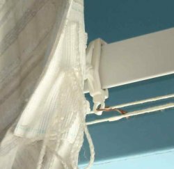
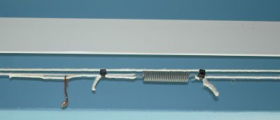
This mechanism is suitable for the plastic or metal flat strip curtain rails only. Two pulleys are used at each end of the rail and a loop of string is passed around the pulleys and kept in place by a tension spring, see below. To get a better "grip" on the string metal pulleys with serrated flanges can be used; alternatively wooden pulleys may be used. The grooves may be slightly ruffled with a file to aid grip.

Curtain Control

The string will always travel in opposite directions and a small hook or piece of wire is attached to each end fastener of each curtain and also to opposite sides of the string loop, see below.

Curtain Control

Each pulley is spaced from the wall with a bracket or small piece of wood. This is supported by a bracket or block of wood. A small Axel passes through each bracket, one end will have a collar, see below, the other end will have a gear that is driven by the motor.

Curtain Control

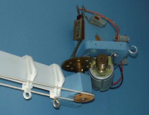
At the motor end, I used two pieces of wood screwed together for the bracket. This now allows the motor to be moved away from the driven gear and un-mesh the gears. As each curtain is attached to the loop, moving just one curtain also moves the other curtain on the loop.

Curtain Control

Friction - Friend or Foe ?

This mechanical design relies on one important property and that is friction. If there is too much friction the motor may not move the curtains at all and the pulleys may just slip. If there is not enough friction in the loop applied by the tension spring, the motor will drive the pulleys which will just turn and not move the loop at all. To overcome this, I use a silicone based furniture polish on the plastic rail, this reduces friction greatly and allows easy movement of the curtains along the loop. To tension the loop of string, fasten one end first to the spring then pull the free end of the string to tension the spring and fix it with cable fasteners or glue, see below.

Curtain Control

This may require some adjustment to get right. To answer the heading friction in this case is both friend and foe, as the spring requires friction, the motor does not. The motor with drive engaged is shown below.

Curtain Control

Depending on the length and weight of the curtains, the motor may have to be changed. I used a 12V hobby motor from Maplin electronics, I had to slightly enlarge the motor shaft with some brass tubing available from most hobby shops. The torque of the motor was not great, but if the output speed is reduced with gears, the torque (twisting force) is increased by the same amount. A worm gear has 1 tooth, and I used a 57 tooth gear, giving a reduction speed of 57:1. The torque of the motor (at the 57 tooth gear) is now increased 57 times. A light grease or machine oil may be applied to the gears, too much and it will splatter all over the walls and curtains!

Setting Up

This is best done with the curtains open, and motor gear unmeshed. Move one of the curtains by hand. They should move easily and meet in the centre of the rail, if not apply some silicone polish to the rail and alter the fastening on the wire.

Next switch the circuit to manual. With the curtains open, press the close switch. The curtains should start to close as long as the switch is pressed and stop moving when the switch is released. Then press the open switch. The curtains should now move as before but in the opposite direction. If all is well, open the curtains with the switch and then fully close them and use a watch to time this. The motor should be sufficiently slow and take a few seconds (about 3 in my case but my room is small).

Finally open the curtains, adjust the preset P1 to minimum resistance and set S3 to automatic. Press the close switch, the motor will run for a second or so and curtains will start to close. Switch back to manual and open the curtains, increase P1 slightly and switch back to auto and press close again. Repeat until the timing is sufficient for the curtains to close. Now press open (with S3 still in manual) the curtains should be timed to open fully.

Final Words

Should you have problems with this circuit, you first need to determine if its mechanical or electrical. Mechanical problems will happen on both manual and automatic settings, and be related to the opening or closing mechanism in general.

If electrical, check the power supply first, then L1 and L2 indications. If nothing works at all build the single manual relay circuit above and once perfected, return to the automatic version.

I am not mechanically minded so any suggestions or improvements towards a better mechanism can be included here; or if any of you have also made electric curtains, I will be happy to display your work.

Alternating Flasher Circuit Diagram

Alternating Flasher Circuit Diagram

This circuit uses three easily available 555 timer ICs. All three work as astable multivibrators. The first 555 has an on period and off period equal to 1 sec. This IC controls the on/ off periods of the other 2 555s which are used to flash two bulbs through the relay contacts.
The flashing occurs at a rate of 4 flashes per second.
The diodes are used to protect the 555 ICs from peaks. The relays should have an impedance greater than 50ohms i.e, they should not draw a current more than 200mA.
The flashing sequence is as follows:
The bulb(s) connected to the first relay flashes for about 1 sec at a rate of 4 flashes per second. Then the bulb(s) connected to the second relay flashes for 1 sec at a rate of 4 flashes per second. Then the cycle repeats.
The flashing rates can be varied by changing the capacitors C3 and C5. A higher value gives a lower flashing rate.
Note that the values of C3 and C5 should be equal and should be less than that of C1.
The value of C1 controls the change-over rate ( default 1sec). A higher value gives a lower change-over rate.
If you use the normally open contacts of the relay, on bulb will be OFF while other is flashing,and vice versa.
If normally closed contacts are used, one bulb will be ON while the other is flashing.

Alternating Flasher Circuit Diagram

Alternating Flasher Circuit Diagram

Circuit Diagrams2

UML, Circuit Diagrams, and God's Rules

Very few software engineers use UML symbols to design software, but electrical engineers regularly use circuit symbols to design electronics:

Circuit elements

Circuit symbols are constructed into circuit diagrams-- the the visual language of electricity:

a circuit diagram

If circuit diagrams are a standard, universally understood way to talk about electronics, why doesn't UML enjoy the same currency for software development?

Well, one obvious difference is that software, unlike electricity, isn't subject to God's laws.* And God didn't invent x86. Software development is far less amenable to formal diagrams because, well, it's something we just made up. And we keep changing the rules all the time. As Brooks points out in The Mythical Man-Month, software developers are essentially playing the role of God:

Why is programming fun? What delights may its practioner expect as his reward?

First is the sheer joy of making things. As the child delights in his mud pie, so the adult enjoys building things, especially things of his own design. I think this delight must be an image of God's delight in making things, a delight shown in the distinctiveness of each leaf and each snowflake.

Second is the pleasure of making things that are useful to other people. Deep within, we want others to use our work and to find it helpful. In this respect the programming system is not essentially different from the child's first clay pencil holder "for Daddy's office."

Third is the fascination of fashioning complex puzzle-like objects of interlocking moving parts and watching them work in subtle cycles, playing out the consequences of principles built in from the beginning. The programmed computer has all the fascination of the pinball machine or the jukebox mechanism, carried to the ultimate.

Fourth is the joy of always learning, which springs from the nonrepeating nature of the task. In one way or another the problem is ever new, and its solver learns something: sometimes practical, sometimes theoretical, and sometimes both.

Finally, there is the delight of working in such a tractable medium. The programmer, like the poet, works only slightly removed from pure thought-stuff. He builds his castles in the air, from air, creating by exertion of the imagination. Few media of creation are so flexible, so easy to polish and rework, so readily capable of realizing grand conceptual structures. (As we shall see later, this tractability has its own problems.)

Yet the program construct, unlike the poet's words, is real in the sense that it moves and works, producing visible outputs separately from the construct itself. It prints results, draws pictures, produces sounds, moves arms. The magic of myth and legend has come true in our time. One types the correct incantation on a keyboard, and a display screen comes to life, showing things that never were nor could be.

Programming then is fun because it gratifies creative longings built deep within us and delights sensibilities we have in common with all men.

Software developers do not have a monopoly on creativity. A clever circuit is no less imaginative than a clever algorithm. But software development is a "tractable medium." If we decide the speed of light is not to our liking, we just change it. Imagine the difficulty an electrical engineer would have working on your circuit diagram if, on that diagram, you had changed something fundamental, like the conductivity of copper.

But even with the helpful constraint of God's rules, circuit diagrams are still idealized representations of the final product. You need a printed circuit board to implement the circuit diagram-- and the translation from circuit digram into PCB typically invoves a lot of real-world compromises.

This is not to say that formal software diagramming systems like UML aren't useful in software engineering. They can be. But they'll never be as useful as circuit diagrams are to electrical engineers.

Circuit Diagrams1

Circuit Diagrams

Next Page: Circuit Symbols
Also see: Block Diagrams

Examples of circuit symbolsCircuit diagrams show how electronic components are connected together. Each component is represented by a symbol and a few are shown here, for other symbols please see the Circuit Symbols page.

Example of Circuit Diagram and Stripboard Layout

Circuit diagrams and component layouts

Circuit diagrams show the connections as clearly as possible with all wires drawn neatly as straight lines. The actual layout of the components is usually quite different from the circuit diagram and this can be confusing for the beginner. The secret is to concentrate on the connections, not the actual positions of components.

The circuit diagram and stripboard layout for the Adjustable Timer project are shown here so you can see the difference.

A circuit diagram is useful when testing a circuit and for understanding how it works. This is why the instructions for projects include a circuit diagram as well as the stripboard or printed circuit board layout which you need to build the circuit.

Good and Bad Circuit Diagrams

Drawing circuit diagrams

Drawing circuit diagrams is not difficult but it takes a little practice to draw neat, clear diagrams. This is a useful skill for science as well as for electronics. You will certainly need to draw circuit diagrams if you design your own circuits.

Follow these tips for best results:

  • Make sure you use the correct symbol for each component.
  • Draw connecting wires as straight lines (use a ruler).
  • Put a 'blob' () at each junction between wires.
  • Label components such as resistors and capacitors with their values.
  • The positive (+) supply should be at the top and the negative (-) supply at the bottom. The negative supply is usually labelled 0V, zero volts.
    If you are drawing the circuit diagram for science please see the section about drawing diagrams the'electronics way'.
If the circuit is complex:
  • Try to arrange the diagram so that signals flow from left to right: inputs and controls should be on the left, outputs on the right.
  • You may omit the battery or power supply symbols, but you must include (and label) the supply lines at the top and bottom.

The same circuit drawn two different ways

Drawing circuit diagrams the 'electronics way'

Circuit diagrams for electronics are drawn with the positive (+) supply at the top and the negative (-) supply at the bottom. This can be helpful in understanding the operation of the circuit because the voltage decreases as you move down the circuit diagram.

Circuit diagrams for science are traditionally drawn with the battery or power supply at the top. This is not wrong, but there is usually no advantage in drawing them this way and I think it is less helpful for understanding the circuit.

I suggest that you always draw your circuit diagrams the 'electronics way', even for science!